The Wireless G Plus MIMO USB Network Adapter easily connects your USB-equipped desktop or notebook computer to your wireless network for Internet and file sharing. Desktop users can now join the network with the ease of a USB plug-in, without opening their PC cases; laptop users can enjoy the benefits of staying... MoreRead more source : http://www.shopping.com/xPO-Belkin-BELKIN-F5D9050-Wireless-G-Plus-MIMO-USB-Network-Adapter
Buffalo Technology Wireless-N Nfiniti™ (WLI-U2-G300N) USB Wifi
Buffalo Nfiniti Wireless-N USB 2.0 Adapter is designed to stream High-Definition (HD) video, voice and music. This wireless USB adapter is a high performance USB solution with a built-in antenna for maximum performance and range. It offers a simple way to connect a Windows® Notebook or PC to a wireless network.Read more source : http://www.shopping.com/xPO-Buffalo-Technology-Nfiniti-Wrls-N-USB-2-0-Keychain-Adapter
U.S. Robotics MAXg™ USR5421 802.11g/b Wireless Adapter USB Wifi
The U.S. Robotics USR5421 Wireless MAXg USB Adapter provides high-performance and secure wireless connectivity for desktop computers. Featuring MAXg technology, this USB adapter provides excellent range to maintain solid connections throughout your home or small business. In addition, it offers data transfer rates of... MoreRead more source : http://www.shopping.com/xPO-U-S-Robotics-USR-WIRELESS-MAXG-USB-ADPT
Three-Phase Full Wave Bridge Rectifier Circuit Diagram
A rectifier is an electrical device that converts alternating current (AC) to direct current (DC), a process known as rectification. This almost always involves the use of some device that only allows one-way flow of electrons, a diode. Below schematic diagram shows a Three-Phase Full Wave Bridge Rectifier Circuit Diagram. Each three-phase line connects between a pair of diodes: one to route power to the positive (+) side of the load, and the other to route power to the negative (-) side of the load.

Single Supply Precise Full Wave Rectifier Using CA3140 Op-Amp
The schematic diagram below describe a precise full-wave rectifier circuit. The circuit needs only a single supply, make it suitable for battery operated devices.
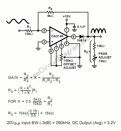


During the positive cycle of the input, the signal is directly fed through the feedback network to the output, give the transfer function of Vout=R3/(R1+R2+R3). At the positive cycle of the input, the diode 1N914 disconnect the op-amp output because the op-amp output is zeroed.
During a negative cycle of the input signal, the CA3140 functions as a normal inverting amplifier with a gain equal to -R2/R1. When the equality of the two equations shown in the Figure is satisfied, the full wave output is symmetrical. Note that the output is not buffered, so the output should be connected only to high impedance stage, with impedance much higher than R3. Errata: the figure shows an equation of GAIN=(R2/R1)=X=(R3/(R1R2+R3)) that is wrong, and the right formula should be GAIN=(R2/R1)=X=(R3/(R1+R2+R3)). [Circuit's schematic diagram source: Intersil Application Notes]
Greatly Expanded Scale Circuit Using LM3914
This is the circuit for bar mode using LM3914 IC for great expanded scale. This circuit is only consists of some resistors circuit. This is the figure of the circuit.

Placing the LM3914 internal resistor divider in parallel with a section (230Ω) of a stable, low resistance divider greatly reduces voltage changes due to IC resistor value changes with temperature. Voltage V1 should be trimmed to 1.1V first by use of R2. Then the voltage V2 across the IC divider string can be adjusted to 200mV, using R5 without affecting V1. LED current will be approximately 10mA. [Schematic source: National Semiconductor, Inc].

Placing the LM3914 internal resistor divider in parallel with a section (230Ω) of a stable, low resistance divider greatly reduces voltage changes due to IC resistor value changes with temperature. Voltage V1 should be trimmed to 1.1V first by use of R2. Then the voltage V2 across the IC divider string can be adjusted to 200mV, using R5 without affecting V1. LED current will be approximately 10mA. [Schematic source: National Semiconductor, Inc].
Swimming Pool Solar Heat Control Circuit
This is a swimming pool solar heating panel pump control. The circuit in below is use an external thermistor that is attached to the solar panel in a manner that will allow it to sense heat generated by direct exposure to the sun. This circuit is controlled by IC TC621-C. This is the figure of the circuit.

A thermistor with a resistance of about 100 kΩ at 25°C should be selected. One such thermistor is the ACW-027 from Ketema, which can be clamped around a pipe in the solar panel. This circuit will energize the pump when the sun is heating the panels and turn off the pump when the sky is cloudy or the sun goes down. To prevent rapid cycling of the pump during partly cloudy conditions, the hysteresis is set for a relatively wide (20°F) span. Providing low thermal impedance between the thermistor assembly and the solar panel will also prevent rapid pump cycling by adding the solar panel’s thermal time constant to the hysteresis. To select the set point resistors, consult the thermistor data sheet for the thermistor’s value at the desired temperature. For example, assume that we want the pump to turn on (high set point) at 100°F and turn off (low set point) at 80°F. [Schematic diagram source: Microchip Technology, Inc].

A thermistor with a resistance of about 100 kΩ at 25°C should be selected. One such thermistor is the ACW-027 from Ketema, which can be clamped around a pipe in the solar panel. This circuit will energize the pump when the sun is heating the panels and turn off the pump when the sky is cloudy or the sun goes down. To prevent rapid cycling of the pump during partly cloudy conditions, the hysteresis is set for a relatively wide (20°F) span. Providing low thermal impedance between the thermistor assembly and the solar panel will also prevent rapid pump cycling by adding the solar panel’s thermal time constant to the hysteresis. To select the set point resistors, consult the thermistor data sheet for the thermistor’s value at the desired temperature. For example, assume that we want the pump to turn on (high set point) at 100°F and turn off (low set point) at 80°F. [Schematic diagram source: Microchip Technology, Inc].
Subscribe to:
Posts (Atom)