Today's portable devices contributed to the smaller, thinner and higher efficiency of electronic devices needs. Now cell phones have become very slim shape, so that the traditional electric-powered loudspeaker has become a mobile phone manufacturers can create as many thin constraints. Ceramic or piezoelectric speakers is rapidly becoming a viable alternative to electric-powered loudspeaker device. These ceramic speakers (drivers) can be slim and compact package provides a very competitive sound pressure level (SPL), which most likely alternative to traditional electricity-powered loudspeaker voice coil.
Ceramic speaker driver amplifier circuit and drive the traditional electric-powered loudspeaker amplifier circuit compared to a different output drive requirements. The structural requirements for ceramic speaker amplifier is capable of driving large capacitive loads, can provide more current at high frequencies, while also able to maintain a high output voltage.
The characteristics of ceramic speakers
Ceramic speaker manufacturers use the technology is very similar to the manufacture of multi-layer ceramic capacitors used in technology. Compared with the electric-powered loudspeaker, the loudspeaker manufacturing technology enables manufacturers to more stringent control over the speaker tolerances. Speakers you want a unified and agreed upon the acoustic characteristics, the rigid structure of tolerance is very important.
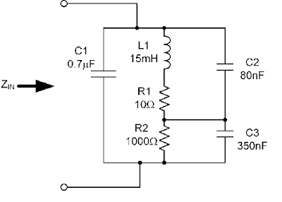
As can be seen from the driver amplifiers, ceramic speaker impedance can be modeled as an RLC circuit, it comes with a large capacitor, this large capacitor is the main component of the model shown in Figure 1. For most audio frequencies, the ceramic speaker is manifested mainly capacitive. This capacitive characteristics of the speaker to express its resistance will decrease with increasing frequency. Figure 2 shows the similarity with 1uF ceramic capacitor speaker impedance and frequency characteristics.
The resistance also has a resonance point. Speakers at the resonant frequency above the audible most efficient point. Decrease in the impedance at 1kHz speaker expressed the resonant frequency.
Relationship Between Sound Pressure, Frequency and Amplitude
The two ends of the ceramic speaker to exert an alternating voltage can make the internal speakers of piezoelectric thin film deformation and vibration, the displacement distance is proportional to the input signal. Vibration of the piezoelectric film to promote the surrounding air, resulting in the sound. Improve the speaker can increase the voltage on the piezoelectric element deflection amplitude, resulting in a greater sound pressure and thus can increase the volume.
Ceramic speaker manufacturers maximum voltage tends to be used to mark their speakers, usually around 15Vp-p. Ceramic devices, said the largest voltage reaches the maximum extension. If the applied voltage is higher than the rated voltage does not produce a higher sound pressure, but it will increase the output signal distortion, see Figure 3.
By comparing the SPL and the frequency and impedance versus frequency curve can be seen in self-resonant frequency of piezoelectric speakers have a large SPL above the most efficient.
Amplifier Requirements.
Ceramic speaker manufacturers typically provides 14 to 15Vp-p of the point of maximum voltage to produce the greatest value of sound pressure. The question now becomes how to generate a single battery supply voltage of these voltages.
One way is to use switching regulators to raise the battery voltage is 5V. With a stable 5V voltage, the system designer can select a needed bridge-tied load (BTL) for single-supply amplifiers. Connected through the bridge can be automatically loads the voltage speaker to see double.
However, the BTL amplifier with 5V output swing theory can only give rise to 10Vp-p. The voltage is not enough to make ceramic speaker output value of the highest SPL. In order to generate higher sound pressure values need to be adjusted to a higher supply voltage.
Another method is to use the boost converter to the battery voltage rises to 5V or higher, but it also has its own problems, such as component size problem. Large peak inductor current will be restricted the size of the overall solution, because in the end of the inductor size must do in order for the physical size of large core is not saturated. Although the small size of the inductor-current market, there are, but the core's saturation current rating may not be sufficiently large to satisfy the high-frequency high-voltage-driven speaker when the load current demand required.
Because ceramic speakers at high frequencies with very low impedance, so when you drive the ceramic components to take into account high-current drive and to avoid the limit.
Chosen to drive the ceramic speaker amplifier must be large enough to drive current in order to avoid driving a large number of high-frequency component of signal-driven speaker into the current limiting mode.
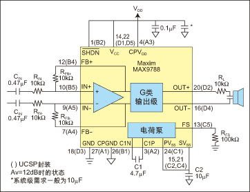
Figure 4 is a Class G amplifier using the application circuit. Class G amplifiers are available multiple voltage rails: a high-voltage and a low voltage. Low-voltage rail used in the output small signal, when the output signal demands for higher voltage swing, the high-voltage rails were switched to the output stage circuit.
Thus, when the output signal is small, G amplifier efficiency than Class AB amplifiers high, due to a lower voltage rail. Because there is a higher voltage rail, G amplifier can still handle the peak transient signals.
Shown in the figure uses a MAX9788 on-chip charge pump to generate a negative voltage and the VDD opposite. The negative voltage rail only require a higher voltage output signal when added to the output circuit on the rail. Boost converter and method of using the traditional Class AB amplifiers, the device can be more efficient to drive ceramic speakers.
Loudspeaker manufacturers often recommend and ceramic speaker series with a fixed resistor (RL), as shown in Figure 4. The resistor in the signal that contains a large number of high-frequency components can limit the amplifier output current.
In some applications, if the restrictions sent to the speaker of the audio frequency response of bandwidth to ensure that the speaker is not short-circuit of the amplifier, you can not have this fixed resistor. Ceramic speakers currently on the market value of the 1uF capacitor of magnitude or so. Speaker as the impedance at 8kHz when 20W, at 16kHz when 10W. Future ceramic speakers may have a larger capacitance value, will force the signal amplifier at the same frequency to provide more current.
Ceramic speaker and the efficiency of electricity-powered loudspeaker.
The efficiency of traditional electricity-powered loudspeaker is easy to calculate. In electrical windings on the coil can be modeled as a fixed resistor in series a large inductor.
You can use the speakers resistance value calculated in accordance with Ohm's law to provide power to the load:
P = I2R, or P = VxI
The power consumption of the speaker coil heat.
As the ceramic speaker's capacitive characteristics, they are power consumption when not produce too much heat. According to the dissipation coefficient of ceramic components, such speakers consumption of so-called reactive power (blind power) is very small. Therefore, the consumption of reactive power generated when the heat is very small.
Can not use a simple calculation of P = VxI reactive power
Reactive power should it be calculated as follows:
P = (πfCV2) × (cosΦ + DF)
Where: c = capacitance value of the speaker; v = RMS driving voltage; f = the frequency of driving voltage; cos j = "current through the speakers, and speakers on the phase angle between the voltage"; Df = speaker dissipation factor, depends on the signal frequency and ceramic speakers ESR.
For an ideal capacitor, the voltage and current between the phase angle should be 90 degrees, while the ceramic speaker is mainly capacitive characteristics, so cos j is equal to 0, that is not part of the ceramic speaker's capacitive power. However, the non-ideal characteristics of ceramic materials will lead to lag behind the voltage on the speaker through the speaker of the current phase angle between them is not equal to 90 degrees. The ideal 90-degree phase shift and the actual difference between the phase shift is the dissipation coefficient. Ceramic speakers in the Df can be modeled as a small resistance, ESR, and an ideal capacitor in series. (Do not series resistance and the isolation between the amplifier and speakers to confuse resistance) Df is the target frequency, the ratio of ESR to the capacitive reactance (Reference 2 and 3):
DF = RESR / XC
For example, a 1.6uF capacitor and the speaker 1W ESR being 5Vrms, 5kHz signal when driving reactive power is:
P = (π × 5000 × 1.6e-6 × 52) × (0 + 0.05) = 31.4mW or 31.4mW.
Real Power
Thus, while the ceramic speaker itself does not like the electric-powered loudspeaker, as the actual power dissipation by thermal methods, but the driver amplifier output stage, and is located between the amplifier and speaker external resistor (RL) could give rise to heat (Figure 4).
An external resistor the greater the amplifier will generate more power, thus affecting the low-frequency response.
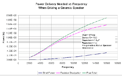
In the drive with a 10W series resistance of the ceramic speaker, we can see that the reactive power has little effect on total load power. Most of the power consumed by an external resistor, see Figure 5 shows the amplifier power and frequency curve.
Better low-frequency response for a smaller external resistor, but this will cause the amplifier output stage power consumption increase. Amplifier efficiency shows how much power consumption in the amplifier output stage. Driven right amplifier power, including class and G class D amplifier, including the demand for more efficient solution, due to the load formed by a number of series resistance, it will load on the network rather than the speaker to generate a certain power. Even if the efficiency of 100% of the amplifier, series resistance will be consumed is supposed to give the speaker power.
In this simple example, 5kHz provided to the load point of the total power is 515mW. Efficiency of 53% of the amplifier will consume 457mW of power. The necessary power amplifier the size of the device can determine the size of the package used. If you must use high-frequency sine-wave-driven speaker, it requires a great deal of power.
In short, the increasingly thin portable devices contributed to the small size ceramic speaker needs. This speaker is different from the traditional electricity-powered loudspeaker, so designers need to consider different design elements. Ceramic speaker's capacitive properties require amplifiers with high output voltage drive and large output current capability, so that the entire frequency range in order to maintain a high voltage.
Chosen to drive the ceramic speaker amplifier must be able to mix the load while providing reactive power and real power. Amplifier efficiency must be high enough to ensure small size and low cost programs.
Therefore need to use different from the traditional Class AB amplifiers amplifier topology. For example, Class G and Class D amplifiers and other more efficient solutions are becoming more attractive, in which G amplifier can provide the best efficiency.
Translate from http://www.eeworld.com.cn/mndz/2008/0625/article_52.html
 Figure 1. Ceramic speaker models.
 Figure 2. The speakers and 1uF ceramic capacitor impedance and frequency characteristics.
 Figure 3. Frequency Characteritics of Sound Pressure Level.
 Figure 4. Schematic amplifier Class G
 Figure 5: the necessary relationship between power and frequency
0 comments:
Post a Comment